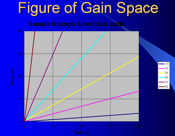
An antagonistic controller in our system consists of two ideal angular springs arranged in opposition. The above figure plots the gain on one spring vs. the gain on the other spring for a sample limb. Each line in this diagram corresponds to one angle of the limb. We name these lines "iso-angle" lines. The angles of these sample lines are shown to the right. For example, any gains on the yellow line will hold the limb at 30 degrees. The tension of a limb can be varied while holding the limb at a given angle by moving along an isoangle line. Tension is lowered by moving towards the origin, increased by moving away from it.
This example explains how a limb is moved using antagonistic control. For this example, we will consider only a single degree of freedom, but the same principle is applied to mutliple dofs.
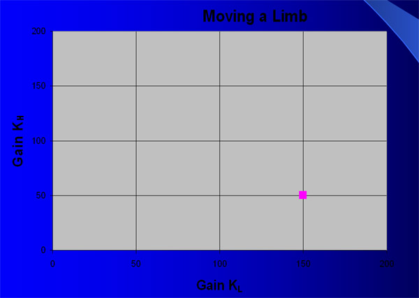
The starting position for the limb corresponds to a point in gain space. The two gains described by this point will hold the limb at the starting point of the movement. The figure above shows the starting gains for a limbs movement.
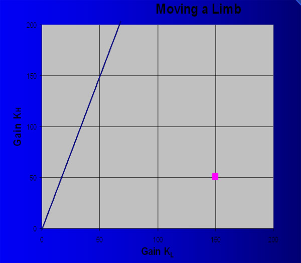
The end position the limb is moved to corresponds to an isoangle line in gain space. This line is calculated taking into account gravity and any other forces acting on the limb. Gains anywhere on the line will hold the limb at the desired end position. The calculated isoangle line for this example is shown in blue in the above diagram.
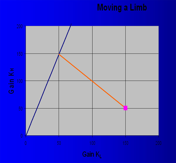
At this point, we have the starting gains for the limb and a line which defines the potential end gains for the limb's movement. The problem remains to determine which end gains to use. If the movement is to be kept essentially linear, a line of slope -1 is drawn from the start gains to the terminal isoangle line, as shown above. The limb is moved by varying the gains along this line. A transition function can be layerd on top of the line to vary the envelope of the movement. The terminal point on the final isoangle line can be varied to control the shape of the movement. More details on this are provided in the paper.
![]()
The tension used in a movement determines how closely a transition function is tracked. In the above figure, the red line corresponds to a high tension (high gain) tracking of transition function. It provides very close tracking of the transition function. The low tension line much more loosely tracks the transition function. Notice that the upward movement lags behind the trajectory initially due to the impact of gravity and momentum. At the end of the movement, the trajectory is overshot, before the limb eventually returns to the desired final position.
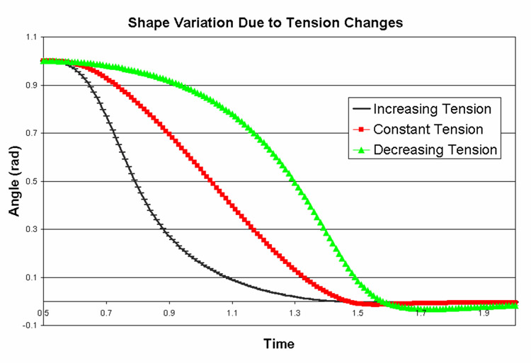
The above figure shows the effect of varying tension during a movement. (This corresponds to changing the intersection point on the terminal isoangle line.) The red line shows constant tension. The limb is closely tracking the ease-in ease-out input function. The black line shows an increase in tension. Notice that the angle of the limb moves more quickly during the beginning of the movement and more slowly at the end. The green line shows a decrease in tension. Here, the angle changes more slowly at the beginning and quickly at the end. Notice also the overshoot that occurs.